Where the Force Goes
The path that explains every member you can see
Following a load from a wheel through the deck, into the floor beams, out through the truss and down to the abutment. The path that explains every member you can see.
A wheel rolls onto a covered bridge and something has to happen to the weight. It does not disappear; it travels — through a sequence of members, each shaped and positioned to pass the load along and, finally, into the ground. Follow that path and the bridge stops looking like a box of timber and starts making sense.
The wheel sits on a plank. Several planks span longitudinally between floor beams — the stout timbers that run side to side across the full width of the bridge, typically spaced a few feet apart along its length. Load from the plank presses down on whichever floor beam lies beneath it, or is shared between two if the wheel falls between them. So far nothing is complicated: short spans, simple bending, end grain bearing on something solid.
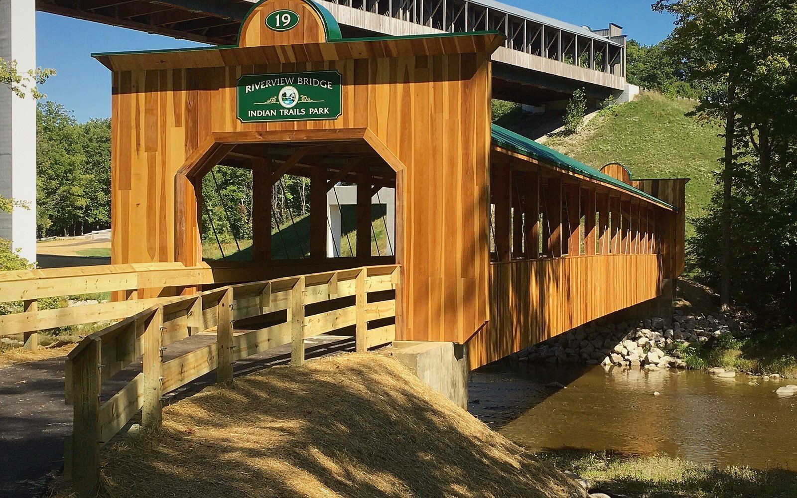
The floor beams must themselves be held up. Their ends sit on, or are framed into, the bottom chord — the long horizontal member that runs the full length of each truss. The chord takes that point load and carries it as part of a larger tension or compression regime running the whole length of the span. This is where the geometry of the truss does its real work: a triangulated frame converts vertical loads into forces that travel along inclined and horizontal members, so that bending — the destructive enemy of long timber beams — is replaced by tension and compression, which wood handles far more efficiently.
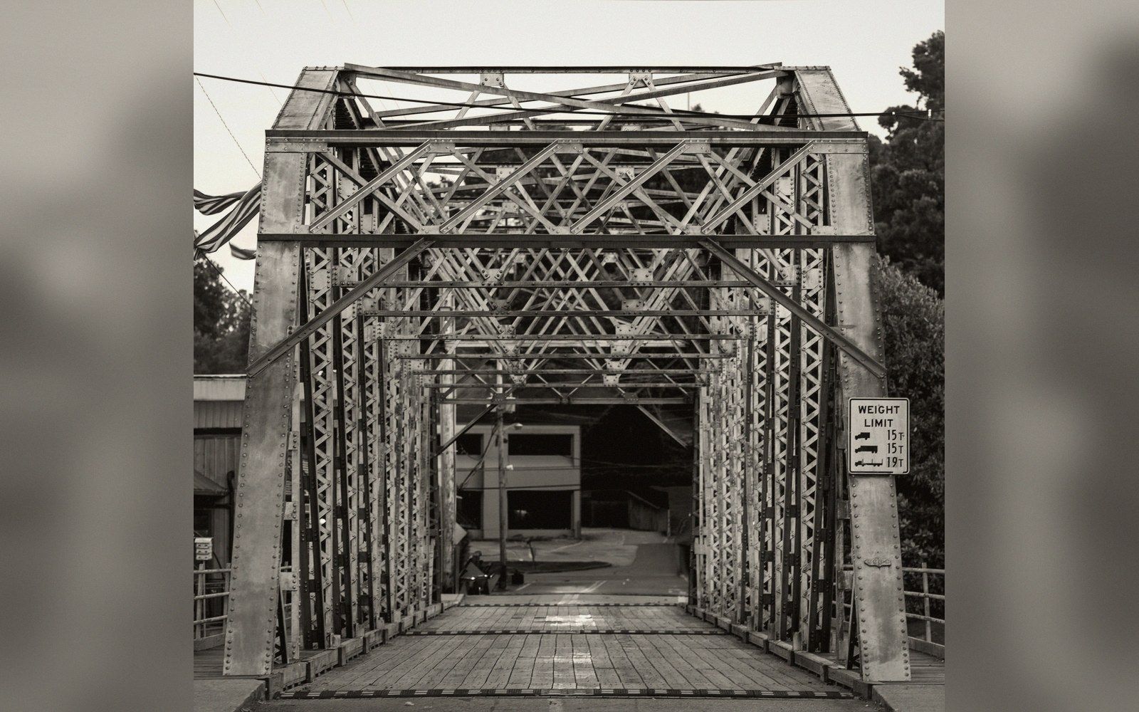
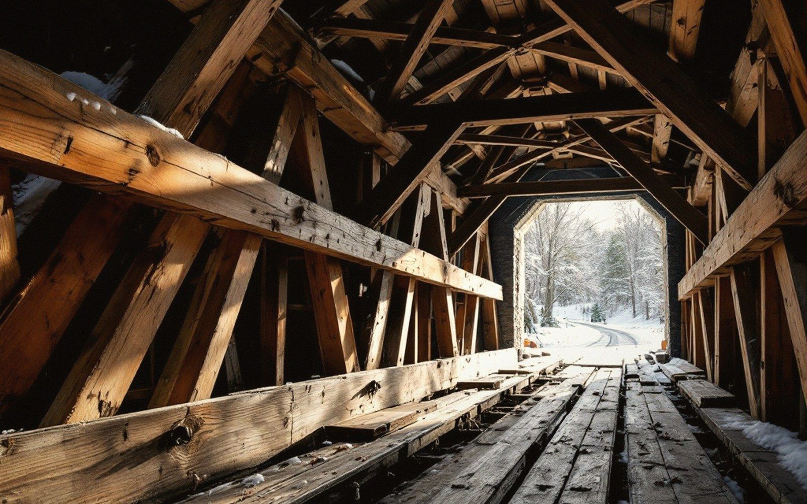
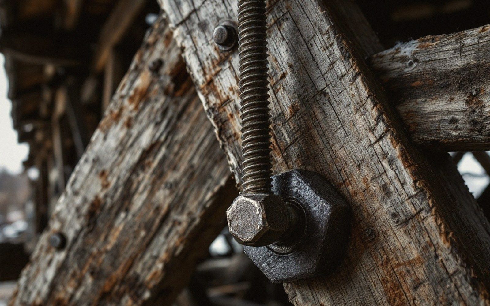
Whether the web members above the chord are in tension or compression depends on the truss type. In a Howe configuration the diagonals are in compression and the vertical iron rods take the tension; reverse it and you have the Pratt. In a Town lattice the web is a continuous criss-cross of planks, spreading load across dozens of intersections rather than funneling it through a handful of joints. In a Burr arch an arch superimposed on a truss shares the load between two structural systems simultaneously. The geometry differs; the logic does not: get the force into the abutment.
The geometry differs; the logic does not: get the force into the abutment.
The upper chord, or the arch if there is one, works in compression. Load arriving from the web pushes outward and downward. The top chord carries it toward the end of the span; the arch carries it along its curve. Either way, the destination is the same — the bearing point where the truss meets the abutment, the stone or concrete seat built into the bank at each end of the bridge.
At that bearing point the entire accumulated weight of the span, plus whatever traffic is crossing it, transfers from wood to masonry. A relatively small area of end grain or metal hardware sits against the abutment; everything that happened along the length of the bridge arrives here. This is exactly where decay concentrates: moisture collects at the interface of two dissimilar materials, end grain wicks water readily, and the ends of chords are the first timbers to soften. The structural logic of the span and the pathology of its failure share the same address.
The roof matters to this story only indirectly. It does not carry the traffic load; it keeps water off the members that do. Dry timber stays strong; wet timber decays at its connections, and connections are precisely where forces change direction. A chord end that is also a bearing point that is also chronically damp is a member under load and under biological attack at once.
That is the whole argument for the enclosure. Every redundancy the builder introduced — the extra diagonal, the supplementary arch, the heavy floor beam — is only as durable as the moisture environment around it. A roof is how a structure that relies on triangulated geometry protects the joints where the geometry does its work. Watch a truck cross an old covered bridge slowly enough and the slight flex visible in the siding tells you the path is still intact. The force still knows where to go.
Dry Timber is an independent publication about covered-bridge engineering. It is not a visitors bureau, tourism body or preservation society.
More in Load
Where the force goes, and what fails first.