Howe and Pratt
Two trusses, one insight
Which members take tension and which take compression — the distinction that decides where iron replaces wood.
In any triangulated frame, every member is either being pulled apart or squeezed together. That distinction — tension versus compression — determines what the member should be made of. The Howe and Pratt trusses are, in essence, two opposite answers to the same question.
Both designs use the same basic geometry: horizontal top and bottom chords, vertical members, and diagonal members. The difference is which diagonals run which way, and therefore which members carry which kind of force.
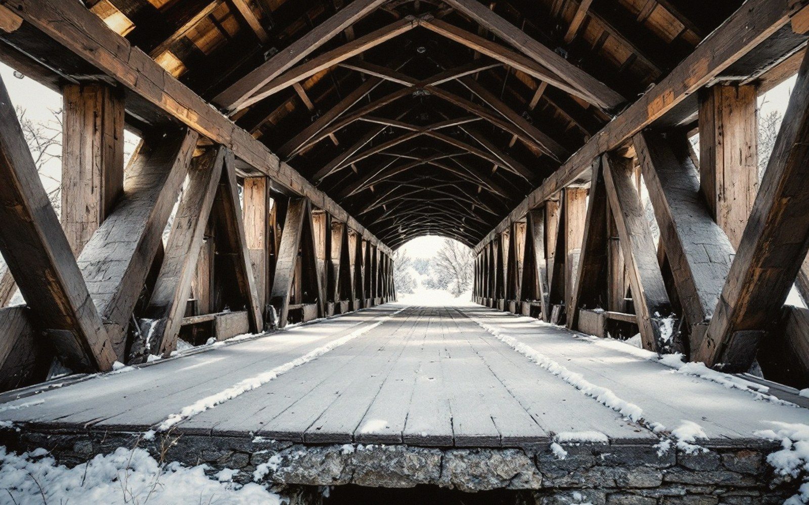
In a Howe truss, the diagonals slope inward toward the center of the span — that is, they lean toward the middle from each end. Under a load, those diagonals go into compression, and the verticals go into tension. William Howe patented his design in 1840, and its great practical advantage was immediate: verticals in tension can be iron rods, adjusted with a threaded nut. Timber, which handles compression well, takes the diagonals; iron, which handles tension reliably and can be tightened in the field, takes the verticals. The combination was efficient enough that railroad builders adopted it almost at once.
The Pratt truss reverses the logic. Thomas Pratt and his father Caleb patented their version in 1844. Here the diagonals slope outward from the center, which puts them in tension and sends the verticals into compression. In a timber bridge that arrangement is less convenient — tension diagonals in wood are harder to connect reliably than compression ones — but in an iron or steel structure, where long slender members handle tension far better than compression, the Pratt geometry eventually became the dominant choice for metal bridges.
In a Howe truss, the diagonals slope inward toward the center of the span — that is, they lean toward the middle from each end.
For covered-bridge builders working primarily in wood, the Howe arrangement held the clear advantage: iron rods as verticals were easy to source, easy to install, and easy to retighten as the timber settled and shrank. The diagonals, doing compression work, stayed wood. The result is a hybrid that plays each material to its strength — which is, quietly, the same principle behind every engineered structure that has outlasted its first generation of builders.
More in Trusses
Each type solves a different problem.